Surge Vessels Address Hydraulic Shock
EP Editorial Staff | April 13, 2017
Properly implemented surge vessels can optimize pump/piping-system performance and address hydraulic shock.
By Frank Knowles Smith III and Steve Mungari, Blacoh Fluid Controls Inc.
Damage to pumps and piping systems from hydraulic shock, also known as water hammer, can often result in catastrophic failure, along with expensive repair and downtime.
In the world of petrochemical processes, hazardous conditions resulting from pump damage or line breaks can also bring about significant liability concerns, along with very negative publicity. With many plants and facilities currently in operation without protection against hydraulic shock, what can be done from a maintenance, repair, and operations (MRO) standpoint to avoid this inevitable problem?
The issue
Under steady-state conditions, a plant’s pumping system will tend to operate near the nominal working pressure unless there is change of flow velocity. This change is defined as hydraulic shock and immediate mitigation efforts are needed to prevent damage from occurring.
This fluid acceleration or deceleration can be attributed to several likely causes, with the most common being from either “pump trip,” or sudden valve closure. A pump trip, generated by sudden loss of power to the pump station or by a pump stop without warning, can drop the working pressures near the pump’s discharge side to negative levels and cause possible vapor-pocket collapse.
The sudden valve closure from electrical, hydraulic, or mechanical failure, or from human action, can result in a dramatic increase in pressure at the inlet side of the closed valve. That pressure increase is experienced as high-velocity (potentially exceeding 4,000 ft./sec.) transient pressure waves that will oscillate throughout the piping network unless the transient wave energy can be suppressed.
Pipes that shake violently, even occasionally with restrained piping, and with loud banging noises are the ones typically experiencing hydraulic shock. Pumps and motors are also likely to be damaged concurrently as the transient-pressure energy waves travel back through the pump until the check valve slams shut.
Weak points in the piping network, such as flange connections and pipe elbows, tend to bear the brunt of the pressure wave’s damaging effect and are often the first to break.
In a single-pump system, several transient-mitigation options are available to address the transient wave’s effects. Some of the most popular are surge vessels, air-release/vacuum valves, pressure-relief valves, surge-anticipator valves, and vacuum breakers. Even with an existing facility or pipeline, space is often readily available to accommodate which specific pieces of mitigation equipment are necessary to solve the problem. However, what does the facility do when the plant is pumping in series?
Case in point
A large oil-industry customer, involved with a chemical-process application, was looking for a way to protect their pumping system infrastructure from damage and repair expenses, along with reducing lost product costs from the breaks.
For their application, a booster pump (which requires a minimum of 100 psi NPSH (net-positive suction head) is located approximately 10,000 ft. from a high-pressure injection pump. When power is lost at the booster pump’s location, with the high-pressure pump operating, a transient negative-pressure wave is generated.
This wave causes a sudden pressure drop at the booster pump’s discharge side and travels at approximately 4,000 ft./sec., making contact with the high-pressure pump. In this situation, it’s important to protect the high-pressure pump from cavitation damage and maintain a minimum 100 psi NPSH on the booster pump.
Monitoring and protecting
Should the high-pressure pump trip when the booster pump is running, a high-pressure “up surge” transient pressure wave will be created at the inlet flange of the high-pressure pump. High pressure can also bypass the check valve and cause additional damage.
A properly sized surge vessel, with the sizing calculated through the use of computer surge-analysis software at the high-pressure pump, will accept energy from the pump trip. It will also be able to accept energy (compress vessel gas volume) on a high-pressure pump trip.
On the high-pressure pump trip, the flow will stop, based on the system demand, and will pump dynamic head. However, there is a concern of reversal of flow back through the high-pressure pump from the up-surge transient wave due to check-valve closing time.
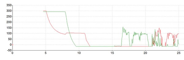
Fig. 1: Negative-pressure transient wave. Graph shows a transient negative-pressure wave on a pump’s discharge side that occurs when power is lost to a booster pump. Green shows booster-pump pressure and red shows high-pressure-pump pressure.
A properly sized surge vessel will accept the transient energy, but check-valve closing time will vary, based on factors such as type of valve and pipe size. With the specific closing time a critical factor to the accuracy of the results from the computer surge analysis, this must be properly entered into the analysis. The results of the analysis can be verified at the time of commissioning using a report from a transient pressure-monitoring system, with the data being read and recorded at a minimum of 100 times/sec.

Fig. 2: Pressure variation without a surge vessel. Fig. 2 shows pressure variation in a system that is not equipped with a surge vessel. Green is the booster-pump pressure and red is high-pressure-pump pressure.
When evaluating how to size a surge vessel to deliver energy, or to keep the high-pressure pump’s NPSH correct in time to de-energize, further computer surge analysis is needed. In this example, the graph in Fig. 2 shows the booster pump tripped (pressure shown in green) while the high-pressure-pump suction pressure is shown in red. In monitoring the liquid level and pressure in the high-pressure pump’s suction-stabilizer surge vessel, the high-pressure pump can be successfully de-energized in 15 sec.

Fig. 3: Surge-vessel pressure at booster pump. Figure 3 shows the pressure inside of a surge vessel at the booster pump.
The pressure drop to the high-pressure pump’s minimum NPSH will keep the pump protected. Figures 3 and 4 show the change in pressure inside the surge vessel placed at the booster pump and at the high-pressure pump.

Fig. 4: Surge-vessel pressure at high-pressure pump. Figure 4 shows the pressure inside of a 106-ft3 surge vessel at a high-pressure pump.
By making use of computer surge analysis to correctly assess the conditions with the booster and high-pressure pump conditions, the customer was able to understand how properly sized and placed surge vessels can assure optimize operational performance by confirming proof of design with transient monitoring of pressure and flow.
With the surge vessels properly located, potential damage to the pumps and piping network from hydraulic shock was eliminated. As a result, considerable time and equipment cost savings were realized.RP
Frank Knowles Smith III is executive vice president of the Surge Control team at Blacoh Fluid Controls Inc., Riverside, CA (blacoh.com). He has three decades of academic, design, and application experience. Steve Mungari is the business development manager at Blacoh. He has more than 20 years of process-control experience in the areas of fluid measurement and control technologies.
POPULAR CATEGORIES
FEATURED VIDEO
-
Featured Video

 VIDEO: Pros And Cons Of Condition Monitoring Services
Brent Nelson is the Director of Product Development for Industrial Services for Donaldson, Bloomington, MN (donaldson.com), a global manufacturer of filtration products and solutions, is our guest for this […]


View Comments