Design Maintainable Hydraulic Systems
EP Editorial Staff | December 8, 2020

The positions and orientation of monitoring devices, service ports, and sensors play a critical role in assuring consistent, cost-saving maintenance.
By Jim Thorington and Brett Nelson, Motion Industries
Component layout in a hydraulic system is critical to maintainability over time. Routinely accessed components must be located such that they are easily serviceable. Designers and fabricators must consider, for example, fluid filters, which require frequent changes. Making the accessibility criterion even more challenging is the desire to make the unit as compact as possible, such as in a mobile application. All of this must be accomplished with safety as the primary concern.
Intentionally designing and fabricating for accessibility will pay future dividends by reducing maintenance costs and protecting workers. By using technology such as 3D-CAD solid modeling, prior to actually assembling the unit, designers can help fabricators find the best component arrangement. There are a number of factors to consider in the design process.
Components
Components with indicators, such as reservoir sight gauges, pressure gauges, and filter-clogging indicators, must be located where the operator can easily see the status. This will help ensure proper machine operation by providing visible alerts when maintenance is required. When continuous machine operation is critical, duplex filters can be used, allowing switching to a clean fluid filter on the fly. The clogged filter then can be changed without shutting down the machine.
Make sure filler breathers are located in a position that allow the operator to easily fill the reservoir when needed. In-tank filters need to be located away from the suction ports, but also positioned in a location that allows the length of the element to be removed from the top. Spin-on return filters often are located on the side of a tank, so removal is easy and a pail can be placed underneath to catch any spillage. While this is the best position for maintenance, the filter’s location in relation to the surroundings should also be considered. If positioned poorly, they can be hit or damaged by other equipment.
Anticipating the need to run electrical power to the unit when it is installed is important, as is knowing where the physical wiring connections and cable/conduit routes are best located for all electrical components. For example, a designer should consider alternate conduit-box location options on electric motors that can make servicing easier, and possibly provide a safer workspace for the electrician.
Ports on reservoirs and valves or components need to be considered in the plumbing plan. Ports require adapters, adapters attach to hose ends, and hoses have a minimum bend radius. All need to be pre-planned to ensure installation goes smoothly.
Is there enough room for two 90-deg. fittings to be installed in two ports next to each other? A common design error is situating the ports too close to one another. Depending on what fittings are selected, choosing the incorrect ones can result in clearance issues, requiring the installer to rework the layout. This ultimately results in more labor/time spent getting permission to make changes, ordering new parts (usually overnight shipping), changing BOMs, and changing prints. A properly planned layout will provide a clean and neat appearance with the plumbing of any hydraulic system and can save a lot of headaches for the person who performs the actual plumbing.
Avoid using National Pipe Tapered (NPT) ports and fittings. NPT threads can leak—larger pipe sizes are particularly hard to seal properly. Instead, use SAE (O-ring sealed), JIC (37-deg. flared), or Code 61/62 (O-ring sealed four-bolt flange) connections. Face-seal-type fittings are also increasing in popularity as a zero-leak fitting option.

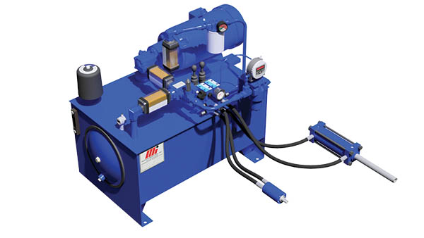
When designing and positioning hydraulic assets, the position of components such as reservoir sight gauges, pressure gauges, and filter-clogging indicators plays a major role in assuring that asset status is consistently monitored. 3D modeling prior to fabrication/assembly is recommended.
Thinking of the Future
Adding pressure and temperature gauges, flow meters, temp/level switches, and filter indicators increases cost. However, they can more than pay for themselves by making it easy to recognize operating trends under normal conditions.
Consider adding an additional pump/motor station as a spare. This obviously adds more initial cost for the power unit, but having a spare pump available in the event another pump/motor has a failure can save significant downtime costs. The cost of downtime for repair should be factored into any decision that involves continuous-
operation assets.
Is future system expansion possible? It’s much more efficient to add an extra suction port and plug it if it is not needed initially than to rework the reservoir later to accommodate expansion.
Physical Access and Safety
While a goal is to keep maintenance costs as low as possible, designers and fabricators often overlook layout concerns that affect personnel safety and hazard prevention. Safety should be a priority in any design.
Designers must consider what tools are required to build and service the unit, and leave space for body, hands, and tools to perform periodic maintenance and repairs. When covers or doors are required, quick-release fasteners simplify removal. Consider including windows or cutouts to allow easy gauge/indicator monitoring. Also provide adequate space so that subassemblies can be removed/replaced.
With today’s IIoT technology, sensors are available to wirelessly transmit diagnostic information for monitoring in a safe environment away from the machine. Beyond filter-clog indicators, the designer should consider adding sensors for fluid-condition monitoring, because the majority of hydraulic system failures are caused by fluid contamination. These can include temperature transducers, particle counters, and water sensors. Flow sensors can help monitor piston-pump health and, therefore, predict a costly/catastrophic pump failure. Another technique is to use remote hydraulic or electronic sensors that can be located a distance away from the unit and connected by hydraulic hose or electrical cables.

Ports on reservoirs and valves or components need to be considered in the plumbing plan. Ports require adapters, adapters attach to hose ends, and hoses have a minimum bend radius. All need to be pre-planned to ensure installation goes smoothly.
An Easier Move
How will the system be moved? Does it have designated lift points or fork locations? These must remain clear and accessible, to provide safe installation or removal of the entire unit. Are the lift points designed to handle the weight of the unit, when empty and when filled with oil? Knowing the center of gravity to provide a stable and balanced load-lifting plan is another important safety consideration.
Mobile equipment
Special consideration must be given to mobile equipment, which may require a different structural load, compared with a floor-mounted unit inside a plant or factory. Either way, the design and layout are important to ensure reliable and safe operation for several years. Mobile applications are subject to higher G-forces and structural loads transmitted through the frame or chassis. For example, a poorly designed reservoir that is improperly mounted to a vehicle chassis can bend and flex and will produce stress cracks in the tank, which will cause leaks. Stress cracks can even occur inside the tank, with the welds on the baffle plate, and remain invisible from the outside of the tank.
For gas- or diesel-powered units, knowing where to position the oil filter, fuel filter, dipstick, and even the fuel cap for easy access and service is also very important. If the dipstick is difficult to see and/or access, it is far less likely that it will be checked on a regular basis.
On mobile applications, knowing the maximum angle of equipment operation is essential, such that a suction port is still submerged in low-level and/or vehicle-tilted positions. The hydraulic-system mounting location on the vehicle itself is a consideration for operators to be able to see things such as the sight glass or pressure gauges.
Hose routing should always be a top consideration with any system, but particularly with mobile systems. Protect hoses from abrasion and damage. Will there be any hot items such as exhaust mufflers or other hot-surfaced equipment or ovens that could cause a fire if a hose were to burst? Perhaps a fire sleeve is required in special areas if hoses cannot be re-routed.
Intentionally designing a hydraulic system’s components for easy access and for safety is an effective way to think ahead and will save the end user much time and money for years to come. Whether you’re planning equipment upgrades for one unit or for a system, following these recommendations will get you started in the right direction. If assistance is needed, a certified fluid-power specialist can provide valuable help. EP
Jim Thorington is the Director of Engineering for Motion Industries Inc., Birmingham, AL (motionindustries.com). He is a Registered Professional Engineer and a Certified Fluid Power Specialist.
Brett Nelson is a Product Specialist of Fluid Power, Hose and Fittings, and Process Pumps at Motion Industries. He has more than 30 years of experience, including 18 years as a hydraulics design engineer.
POPULAR CATEGORIES
FEATURED VIDEO
-
Featured Video

 VIDEO: Pros And Cons Of Condition Monitoring Services
Brent Nelson is the Director of Product Development for Industrial Services for Donaldson, Bloomington, MN (donaldson.com), a global manufacturer of filtration products and solutions, is our guest for this […]


View Comments