Bust Nine Common Motor Myths
EP Editorial Staff | June 16, 2021

Here are the facts about some of the things “they” say about motors and motor performance.
By Thomas H. Bishop, P.E., EASA Inc.
The tongue-in-cheek saying “If it’s in black and white, it must be right” is a helpful reminder that not everything we read (or hear) is accurate or complete. It’s always best to check sources and verify facts before accepting consequential statements as true. A similar adage underscores the importance of this advice in the digital age: “If it’s on the Internet, it must be true.” With these things in mind, here’s a random collection of common misconceptions about three-phase squirrel-cage motors and the facts that deny them.
Soft-starting motors reduce utility demand charges.
Soft starters typically ramp up the voltage applied to a motor over a few seconds at start-up, reducing winding heating and starting current. This may extend the life of the winding for motors that start frequently, but it doesn’t affect utility demand charges. That’s because the electric meter averages the kilowatts consumed over each 15-to-30-min. period, not just for the few seconds that the soft starter reduces input power to the motor.
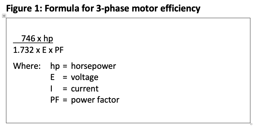
Higher current means a motor is less efficient.
Input power is not a function of current alone. Other factors are voltage, power factor, and efficiency. As an example, Table 1 shows the key data for two 460-V motors of the same 75-hp (55-kW) rating.

Note that Motors A and B have the same full-load efficiency despite a difference of more than 3 A in their ratings. If you want to fact-check this, use the formula in Figure 1.
Power-factor-correction capacitors can reduce motor energy consumption.
Applying power-factor capacitors at the motor terminals increases the power factor on the supply cables but does not change the motor’s power factor. Increasing the power factor on the supply lines reduces current in them, causing a corresponding but typically insignificant reduction in I2R losses (energy) in the supply wiring. The primary reason for reducing supply-circuit current is to add electrical loads without rewiring a facility.
A motor can be loaded up to its service factor current.
An example of this would be loading a 1.15 service-factor motor up to its service-factor current (typically ~1.15 x rated current). That would be a problem, according to clause 14.37.1 of NEMA Stds. MG 1-2016: Motors and Generators (MG 1): “A motor operating continuously at any service factor greater than 1 will have a reduced life expectancy compared to operating at its rated nameplate horsepower. Insulation life and bearing life are reduced by the service factor load.”
Further, the service factor only applies to Usual Service Conditions (MG 1, 14.2). These include operation at an ambient temperature of 5 F to 104 F (-15 C to 40 C) and at an altitude of less than 3,300 ft. (1,000 meters) when rigidly mounted in areas or supplementary enclosures that do not seriously interfere with the machine’s ventilation.
A 230-V motor can be used on a 208-V electrical system.
Per MG 1, 12.45, motors can operate successfully at ±10% of their rated voltage. Since 10% below 230 V is 207 V, a 230-V motor would appear to be acceptable for use on a 208-V system. But ANSI Std. C84.1 permits service entrance voltage for 208-V power systems to be as low as 191 V. Since there will be additional voltage drop in the building wiring, the voltage supplied to the motor could be less than 191 V—well below the 207-V minimum required for the 230-V motor.
If the motor has a nameplate rating of 208 to 230 V, ask the manufacturer for a suitable voltage range. Said another way, ask if the manufacturer’s warranty will apply if the motor is used anywhere between 187 V (208 V minus 10%) and 253 V (230 V plus 10%).
Oversized motors, especially motors operating at less than 60% of rated load, are not efficient and should be replaced with appropriately sized premium efficiency (IE3) motors.
On the contrary, matching motor horsepower (kW) rating to the load will usually mean a slightly lower efficiency at that load than using the next larger sized motor. The reason is that motors tend to peak in efficiency between 75% and 80% load. Motors that drive supply or return air fans in HVAC systems generally operate at 70% to 75% of rated load, making them candidates for use with oversized motors.
Further, even at 60% of rated load (which more than one industrial motor study found to be the average load level), the next higher power rating motor could be more efficient at that load than the appropriately sized power rating. Some high-inertia loads also require more HP/kW to start than to run the load. Reducing the HP/kW to match the running load could result in the motor being unable to start the load.
It doesn’t matter which of the three line-to-line voltages in a three-phase system you measure to see if a motor is supplied with the proper voltage.
It does matter. Voltage unbalance negatively affects three-phase motors. Even modest differences among the three line-to-line voltage levels can increase motor heating considerably. Voltage unbalance is expressed as a percentage and determined by the formula in Figure 2.
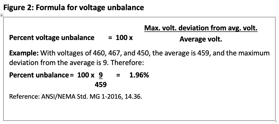
The formula for percentage of additional temperature rise in a motor winding due to unbalanced supply voltages is 2 x (% voltage unbalance)2, so a mere 3.5% unbalance would cause a substantial increase: 2 x 3.52 = 24.5%. For many motors, that would be an additional temperature rise of about 36 F (20 C).
According to a well-accepted guideline, motor-winding life decreases by half for each 18 F (10 C) increase in temperature. Thus the 36 F (20 C) additional temperature rise due to a 3.5% voltage unbalance can cut a motor’s insulation life to about a quarter of what it should be.
Hand contact on a motor surface is a reliable way to judge operating temperature.
Never check a motor’s surface temperature by hand! Modern motors can have surface temperatures near or above the boiling point of water during normal operation. Appropriate devices for measuring these temperatures include thermometers or pyrometers, thermocouples, and thermal imagers.
Note that MG 1 sets specific limits for internal winding temperatures but not for motor surfaces. Where it does address parts other than windings (clause 12.43), it says the temperature of such parts “shall not injure the insulation or the machine in any respect.” Unless the motor surface temperature exceeds the winding’s rating or something on the surface is damaged or otherwise degraded, MG 1 would not consider it too hot.
Winding burnout is the most common cause of motor failure.
Although a winding failure usually results in a more costly repair and longer downtime, bearing failure is the most common cause of motor failure (see Table 2).

Thomas H. Bishop, P.E. is a senior technical support specialist at EASA Inc., St. Louis (314-993-2220; easa.com). EASA is an international trade association of more than 1,800 firms in about 70 countries that sell and service electromechanical apparatus.
POPULAR CATEGORIES
FEATURED VIDEO
-
Featured Video

 VIDEO: Pros And Cons Of Condition Monitoring Services
Brent Nelson is the Director of Product Development for Industrial Services for Donaldson, Bloomington, MN (donaldson.com), a global manufacturer of filtration products and solutions, is our guest for this […]


View Comments