Lubrication 101: Understanding Viscosity
EP Editorial Staff | June 6, 2022

By Mark Barnes, PhD CMRP, Des-Case Corp.
The Stribeck Curve and the Hersey number are your primary tools for selecting proper lubricant viscosity.
For rotating equipment, proper lubricant selection is critical to asset reliability. Done correctly, equipment can live a long and healthy life; done poorly, asset life will be significantly reduced. Of course, original equipment manufacturers (OEMs) have long recognized the importance of using the right lubricant, which is why every operating manual provides a lubricant recommendation and a specific brand or, more often, a few brands from which to choose. However, have you ever stopped to consider the source of those recommendations?

While the heart of lubricant selection is deeply rooted in the complex field of tribology—the study of friction, wear, and lubrication—the underlying principles are straightforward. As a starting point, we need to choose a lubricant with the correct viscosity. Viscosity is the most important property of any lubricant, and its selection is a balance between speed and load. This can best be explained by the Stribeck Curve (Figure 1), first proposed in the early 1900s by Richard Stribeck.
Stribeck discovered that the friction between two interacting surfaces separated by a lubricant could be measured as a function of a compound parameter referred to as the Hersey Number. It is defined as:
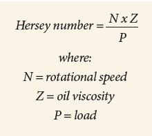
Since the whole purpose of a lubricant is to minimize friction, thereby reducing wear, the Stribeck curve and, in particular, the Hersey number helps us understand the primary lubricant-selection question: What viscosity of oil should I use to minimize friction? As an example, let’s consider lubricant selection for a plain (journal) bearing under high load.
Basic viscosity selection
When the shaft is at rest on the bearing (N=0), the system operating condition is to the far left of the Stribeck curve. As the shaft starts to turn within the bearing, N (speed) is low, and P (load) is high. In other words, the overall friction between the shaft and bearing is high, assuming the machine is not equipped with any form of hydrostatic lifting mechanism. This corresponds to area A in the Stribeck curve, which is referred to as boundary lubrication. Under boundary lubrication, the specific film thickness (λ), which is defined as the ratio of the average separation between the moving surfaces (Figure 2) is less than one.

As speed increases, the operating condition transitions from boundary (the A regime in Figure 1) to the B regime, referred to as mixed film. Under these conditions, the specific film thickness (λ) is close to 1.0, meaning the average separation of surfaces and composite surface roughness are roughly equal. This is the minimum speed for the applied load and viscosity for which true metal-to-metal separation occurs due to oil viscosity.
The last regime is full film, denoted as regime C in Figure 1. Full-film separation is only achieved at very high speeds and/or very low loads and corresponds to λ values exceeding 3.0. Under full-film conditions, there is complete separation between moving surfaces inside the machine. Interestingly, even under full-film separation, friction does not equal zero and, in fact, continues to rise as speeds increase (Figure 1). While this may seem counterintuitive, increased friction under high-speed/full-film separation is due to friction within the lubricant, caused by sliding motion between discrete oil molecules under laminar flow. This is referred to as fluid friction and is one of the reasons why even properly lubricated components generate heat.
Based on the Stribeck curve, we can now start to make sense on many of those OEM viscosity recommendations. For low-speed applications, we tend to use higher viscosity. In high-speed conditions, we choose a lower viscosity.
For journal bearings, such as those found in turbomachinery, lubricant selection is straightforward. Choose a lubricant that, under normal operating loads, speeds, and temperatures, allows the system to operate under full-film hydrodynamic conditions, where λ>3.0. Doing so will minimize mechanical friction and maximize machine life. Most journal bearings of this type use rust- and oxidation-inhibited (R&O) oil with an ISO viscosity grade in the 32 to 68 cSt range.
So lubricant selection is simple: Choose a lubricant such that fluid viscosity at operating temperature corresponds to a Hersey number and hence the specific film thickness that is in the full-film range (regime C in Figure 1)?
Not so fast! While this may work for journal bearings, for other applications we need to consider other factors such as how the lubricant is supplied to the lubricated components and how the machine functions.
Complex conditions
As an example, think about a gear reducer driven by a 1,740-rpm motor, with an output shaft speed of 70 rpm. With such a wide variation in speed how do you chose the right viscosity? While the (high-speed) input-shaft bearing may demand a low viscosity, the slow-speed output-shaft bearing and associated gearing needs a higher viscosity.
But not too high. Since most smaller gear reducers are splash lubricated, we need a lubricant to be fluid enough to be adequately distributed to the internal lubricated components.
In reality, lubricant selection for a gear reducer is typically based on the pitch-line velocity of the slow-speed gear and is a trade-off between viscosity and fluidity. While it is true that, for gearboxes, we select a higher viscosity base oil to try to drive the system to the right-hand side of the Stribeck curve, the reality is, at the low-speed end, most gear reducers are operating under boundary lubrication.
Recognizing this problem, gearbox OEMs usually recommend gear oils fortified with extreme pressure (EP) additives designed to protect moving surfaces under boundary lubrication conditions where λ is less than 1. For the same reason, gearboxes with high reduction ratios usually run hotter because the viscosity “mismatch” between the high speed and low speed shafts generates significant amounts of fluid friction at the high-speed end.
But what about component types such as hydraulics? Hydraulic pumps operate at high speeds so, presumably, we can achieve full-film separation through appropriate viscosity selection? Again, the situation is a little more nuanced. In hydraulic systems, too high a viscosity causes lower mechanical efficiency, leading to increased friction and heat generation that can result in sluggish operation and even poor lubrication due to reduced flow rates. Likewise, some of the parts we are trying to lubricate, for example the ring-to-vane clearance in a vane pump, are a pressure seal, meaning that the separation between surfaces needs to be small to generate pressure and prevent internal leakage.
As such, viscosity selection for a hydraulic system is a balance between operational considerations (operating pressures, flow rates, and component types) and the lubricating properties of the oil. In the case of hydraulics, operational considerations usually mean that we need to use an ISO VG 32, 46, or 68 fluid. That means most hydraulic vane or piston pumps operate under mixed-film conditions (regime B in Figure 1). For this reason, most hydraulic fluids contain anti-wear (AW) additive designed to provide increased lubricity when λ is close to 1. EP
Mark Barnes, CMRP, is Senior Vice President at Des-Case Corp., Goodlettsville, TN (descase.com). He has 21 years of experience in lubrication management, oil analysis, and contamination control.
POPULAR CATEGORIES
FEATURED VIDEO
-
Featured Video

 VIDEO: Pros And Cons Of Condition Monitoring Services
Brent Nelson is the Director of Product Development for Industrial Services for Donaldson, Bloomington, MN (donaldson.com), a global manufacturer of filtration products and solutions, is our guest for this […]


View Comments